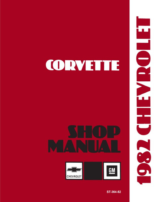
This DIY repair manual by Haynes, covers 1968-1982 Chevy Corvette Stingray models, with V8 engines including the 305, 327, 350, 427, and 454 cu. in. Complete maintenance and repair info for do-it-yourself 'Vette owners who'd like to keep their cars in top-running condition. This manual can also be a great reference for those wanting to restore their Corvettes.
Book Excerpt: 1968-1982 Chevrolet Corvette Repair Manual GENERAL ENGINE OVERHAUL PROCEDURES
PISTON/CONNECTING ROD ASSEMBLY | INSPECTION
(Refer to illustrations 17.4a, 17.4b, 17.10 and 17.11)
MANUAL TRANSMISSION
AUTOMATIC TRANSMISSION
Subject: 1968, 1969, 1970, 1971, 1972, 1973, 1974, 1975, 1976, 1977, 1978, 1979, 1980, 1981, 1982 Chevrolet Corvette service, maintenance, repair. ISBN-10: 1850107238 | ISBN-13: 9781850107231 | Haynes 24040
Book Excerpt: 1968-1982 Chevrolet Corvette Repair Manual GENERAL ENGINE OVERHAUL PROCEDURES
ENGINE OVERHAUL: GENERAL INFORMATION It's not always easy to determine when, or if, an engine should be completely overhauled, as a number of factors must be considered. High mileage is not necessarily an indication that an overhaul is needed, while low mileage doesn't preclude the need for an overhaul. Frequency of servicing is probably the most important consideration. An engine that has had regular and frequent oil and filter changes, as well as other required maintenance, will most likely give many thousands of miles of reliable service. Conversely, a neglected engine may require an overhaul very early in its life. Excessive oil consumption is an indication that piston rings and/ or valve seals or guides are in need of attention. Make sure oil leaks aren't responsible before deciding the rings and / or guides are bad. Have a cylinder compression or leakdown test performed by an experienced tune-up mechanic to determine the extent of the work required. If the engine is making obvious knocking or rumbling noises, the connecting rod and/or main bearings are probably at fault. Loss of power, rough running, excessive valve train noise and high fuel consumption rates may also point to the need for an overhaul, especially if they are all present at the same time. If a complete tune-up doesn't remedy the situation, major mechanical work is the only solution.
PISTON/CONNECTING ROD ASSEMBLY | INSPECTION
(Refer to illustrations 17.4a, 17.4b, 17.10 and 17.11)
- Before the inspection process can be carried out, the piston/connecting rod assemblies must be cleaned and the original piston rings removed from the pistons. Note: Always use new piston rings when the engine is reassembled.
- Using a piston ring installation tool, carefully remove the rings from the pistons. Be careful not to nick or gouge the pistons in the process.
- Scrape all traces of carbon from the top (known as the crown) of the piston. A handheld wire brush or a piece of fine emery cloth can be used once the majority of the deposits have been scraped away. Do not, under any circumstances, use a wire brush mounted in an electric drill to remove deposits from the pistons. The piston material is soft and will be eroded away by the wire brush.
- Use a piston ring groove cleaning tool to remove carbon deposits from the ring grooves (see illustration). If a tool isn't available, a piece of broken off the old ring will do the job (see illustration). Be very careful to remove only the carbon deposits - don't remove any metal and do not nick or scratch the sides of the ring grooves.
- Once the deposits have been removed, clean the piston/rod assemblies with solvent and dry them with compressed air (if available). Make sure the oil return holes in the back sides of the ring grooves are clear.
- If the pistons aren't damaged or worn excessively, and if the engine block isn't rebored, new pistons will not be necessary. Normal piston wear appears as even vertical wear on the piston thrust surfaces and slight looseness of the top ring in its groove. New piston rings, on the other hand, should always be used when an engine is rebuilt.
- Carefully inspect each piston for cracks around the skirt, at the pin bosses and at the ring lands.
MANUAL TRANSMISSION
GENERAL INFORMATION All vehicles covered in this manual come equipped with either a three-speed or four-speed manual transmission or an automatic transmission. All information on the manual transmission is included in this Part of Chapter 7. Information on the automatic transmission can be found in Part B of this Chapter. Due to the complexity, unavailability of replacement parts and the special tools necessary, internal repair by the home mechanic is not recommended. The information in this Chapter is presented if you choose to overhaul the transmission yourself. Depending on the expense involved in having a faulty transmission overhauled, it may be a good idea to replace the unit with either a new or rebuilt one. Your local dealer or transmission shop should be able to supply you with information concerning cost, availability and exchange policy. Regardless of how you decide to remedy a transmission problem, you can still save a lot of money by removing and installing the unit yourself.
SHIFT LINKAGE (1968 AND 1969 THREE-SPEED MODELS): ADJUSTMENT
- Loosen the locknuts on both shift rods.
- Set the shift control lever within the car in Neutral then insert a suitable gauge (0.640 in thick) in the notch of the lever and bracket assembly.
- Move the shift lever on the side of the transmission to Neutral (center detent) position.
- Hold the first / reverse rod and lever against the gauge and then tighten the locknut against the swivel.
- Press second/ third rod and lever against the gauge then run the front nut up against the swivel, finally tightening the rear locknut.
- Remove the gauge and check the shift lever positions. Move the shift lever to neutral and re-insert the gauge into the notch. If the gauge does not freely enter the bracket assembly, re-adjust the linkage.
AUTOMATIC TRANSMISSION
TURBO 350 TRANSMISSIONS | 1978 THROUGH 1981 MODELS
- The detent valve is actuated by the downshift detent cable, which is connected to the carburetor linkage. When the throttle is 1/2 open, the detent valve is actuated, causing a part throttle downshift at speeds below 50 mph. When the throttle is opened completely, the detent valve is actuated, causing the transmission to downshift. The 3-1 valve is actuated, causing the transmission to downshift. The 3-1 detent downshift occurs when vehicle speed is approximately 6 to 12 mph below the maximum throttle 1-2 upshift point. The 3-2 detent downshift occurs when vehicle speed is approximately 4 to 8 mph below the maximum throttle 2-3 upshift point.
- After the cable has been installed on the transmission, install the cable fitting into the bracket on the engine. Note: The slider must not ratchet through the fitting. If it does, depress and hold the metal lock tab and move the slider back (away from the carburetor lever) until it stops against the fitting, and then release the lock tab.
Subject: 1968, 1969, 1970, 1971, 1972, 1973, 1974, 1975, 1976, 1977, 1978, 1979, 1980, 1981, 1982 Chevrolet Corvette service, maintenance, repair. ISBN-10: 1850107238 | ISBN-13: 9781850107231 | Haynes 24040
TABLE of CONTENTS:
- Introduction: Vehicle identification numbers; Buying parts; Maintenance techniques, and more.
- Tune-up and routine maintenance
- Engines (V8): 305, 327, 350, 427, 454 c.i.
- Engine and overhaul procedures
- Cooling, heating and air-conditioning systems
- Fuel and exhaust systems
- Engine electrical systems
- Emissions control systems
- Manual transmission: 3- and 4-speed Muncie, 3- and 4-speed Saginaw, 4-speed Warner
- Automatic transmission: Turbo Hydra-Matic 350, 400. CBC350. 700-R4
- Clutch and driveline
- Brakes
- Suspension and steering systems
- Body
- Chassis electrical system
- Wiring diagrams


