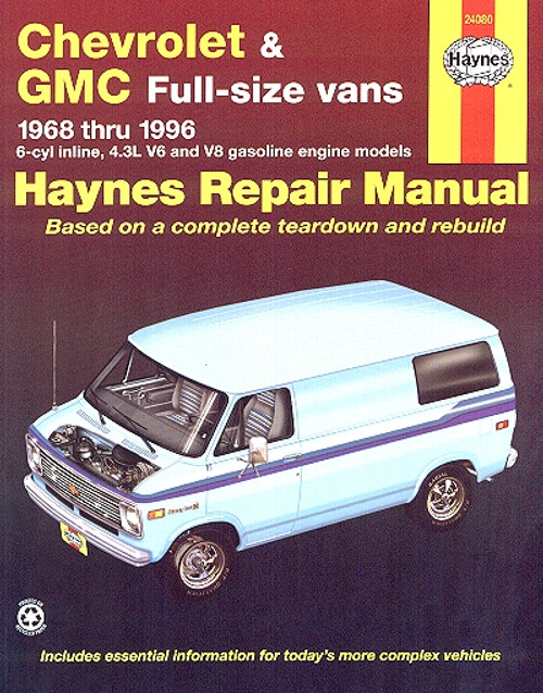
This DIY repair and service manual by Haynes, covers all models of 1968-1996 Chevy and GMC full-size vans powered by inline 6-cylinder, 4.3L V6, and V8 engines, manual and automatic transmissions. Note: This manual does not include 454 or diesel engine information.
Book Excerpt: 1968-1996 Chevrolet, GMC Full-Size Van Repair Manual 6-CYLINDER INLINE ENGINES
ENGINE ELECTRICAL SYSTEMS
Subject: 1968, 1969, 1970, 1971, 1972, 1973, 1974, 1975, 1976, 1977, 1978, 1979, 1980, 1981, 1982, 1983, 1984, 1985, 1986, 1987, 1988, 1989, 1990, 1991, 1992, 1993, 1994, 1995, 1996 Chevrolet, GMC Full-Size Van service, maintenance, and repair procedures. ISBN-10: 1563921979 | ISBN-13: 9781563921971 | Haynes 24080
Book Excerpt: 1968-1996 Chevrolet, GMC Full-Size Van Repair Manual 6-CYLINDER INLINE ENGINES
ROCKER ARM COVER | REMOVAL AND INSTALLATION REMOVAL
- Remove the PCV hose or valve (depending on how equipped) from the rocker arm cover (refer to Chapter 6 if necessary).
- Remove the air cleaner assembly.
- Remove the wiring, fuel and vacuum lines from the rocker arm clips.
- Note which rocker arm bolts are used to retain clips, then remove the bolts, reinforcements and clips.
- Remove the rocker arm cover. If the cover is stuck to the head, do not try to pry it off with a screwdriver or knife. Instead use a rubber mallet to bump the end of the cover or place a block of wood against the end of the cover and hit it with a hammer. If the cover will still not release carefully insert a thin blade knife or gasket scraper under the sealing flange and cut the gasket loose from the head. Use caution not to distort the sealing flange of the rocker arm cover.
- Carefully clean all traces of old gasket and sealer from the sealing flange of the rocker arm cover and the head. Use caution to prevent debris from falling into the oil drain back holes in the head.
INSTALLATION- Check the rocker arm cover sealing flange for straightness and straighten or replace as necessary.
- Using a small amount of RTV sealant in the rocker arm cover to hold it is place, install a new gasket. Do not use sealant on the gasket-to-head surface.
- The remainder of the installation is the reverse of the removal procedures.
ENGINE ELECTRICAL SYSTEMS
IGNITION COIL | CHECK AND REPLACEMENT (Refer to illustrations 9.3, 9.6, 9.11, 9.12a, 9.12b, 9.13, 9.14 and 9.16) REMOTE COIL (MECHANICAL BREAKER POINT SYSTEM)
- Label the wires and terminals, then detach the wires from the coil. Using an ohmmeter, check the resistance of the primary and secondary circuits. It should be about 1 or 2 ohms for the primary circuit and 3K to 20K ohms for the secondary circuit. If the check indicates an open or short in the coil, replace it with a new one by loosening the clamp screw and sliding the coil out of the mounting bracket. Clean the bracket before installing the new coil and don't overtighten the clamp screw. NOTE: since electrical parts normally cannot be returned once purchased, it's a good idea to have your test results confirmed by a repair shop before buying a new coil.
REMOTE COIL (HEI IGNITION SYSTEM) CHECK- Check for voltage at the coil battery terminal with a test light or voltmeter. The ignition switch must be turned to the On position. If no voltage is indicated, check for loose connections at the coil and ignition switch and make any necessary repairs.
- Detach the coil wire harness connector and hook up an ohmmeter as shown in Test 1 (see illustration). If the reading is above 1 ohm, replace the coil with a new one.
- If the reading is 0 to 1 ohm, hook up the ohmmeter leads as shown in Test 2 (see illustration 9.3). If the reading is less than 6000 ohms or more than 30,000 ohms, replace the coil with a new one.
- If it's between 6000 and 30,000 ohms, connect the ohmmeter leads as shown in Test 3 (see illustration 9.3). If the ohmmeter reading is less than infinite resistance, replace the coil. If the reading is infinity, the coil is functional.
REPLACEMENT- If not already done, detach the coil high tension lead and unplug the primary wire electrical connector (see illustration).
- Remove the mounting nuts and separate the coil form the engine.
- Installation is the reverse of removal.
Subject: 1968, 1969, 1970, 1971, 1972, 1973, 1974, 1975, 1976, 1977, 1978, 1979, 1980, 1981, 1982, 1983, 1984, 1985, 1986, 1987, 1988, 1989, 1990, 1991, 1992, 1993, 1994, 1995, 1996 Chevrolet, GMC Full-Size Van service, maintenance, and repair procedures. ISBN-10: 1563921979 | ISBN-13: 9781563921971 | Haynes 24080
TABLE of CONTENTS:
- Introduction: Vehicle identification numbers; Buying parts; Maintenance techniques, and more.
- Tune-up and routine maintenance
- Engine and overhaul procedures
- Cooling, heating and air-conditioning systems
- Fuel and exhaust systems
- Engine electrical systems
- Emissions control systems
- Transmission
- Brakes
- Suspension and steering systems
- Body
- Chassis electrical system
- Wiring diagrams


