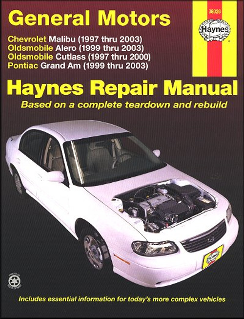
This Chilton DIY repair and service manual, covers 1997-2000 Chevy Malibu, Oldsmobile Cutlass automobiles, U.S. and Canadian models. Like all Chilton manuals available from The Motor Bookstore, this DIY guide provides detailed information with clear photos so you can service and repair your car yourself!
Book Excerpt: 1997-2000 Chevy Malibu, Oldsmobile Cutlass Repair Manual FUEL SYSTEM
SUSPENSION AND STEERING
Subject: 1997, 1998, 1999, 2000 Chevrolet Malibu, Oldsmobile Cutlass service, maintenance, repair. ISBN-10: 0801993202 | ISBN-13: 9780801993206 | Chilton 28690
Book Excerpt: 1997-2000 Chevy Malibu, Oldsmobile Cutlass Repair Manual FUEL SYSTEM
THROTTLE BODY | REMOVAL AND INSTALLTION 2.4L ENGINE (SEE FIGURE 23)
- Disconnect the negative battery cable.
- Remove the air cleaner resonator and outlet hose from the vehicle.
- Detach the connectors from the TP sensor and IAC valve.
- Tag and disconnect the vacuum hoses from the throttle body.
- Remove the throttle, cruise (if equipped), and transaxle control cables from the throttle body.
- Remove the MAP sensor.
- Remove the accelerator cable bracket.
- Unfasten the throttle body attaching bolts, then remove the throttle body from the intake manifold.
TO INSTALL:- Thoroughly clean the throttle body and intake manifold mounting surfaces.
- Position the throttle body onto the intake manifold.
- Install the throttle body retaining bolts, and tighten to 58 inch lbs. (7 Nm).
- Install the accelerator bracket.
- Install the MAP sensor.
- Attach the throttle, cruise (if equipped), and transaxle control cables.
- Connect the vacuum hoses to the throttle body.
- Attach the connectors to the TP sensor and IAC valve.
- Install the air cleaner resonator and outlet hose.
- Connect the negative battery cable.
SUSPENSION AND STEERING
POWER RACK AND PINION STEERING GEAR | REMOVAL AND INSTALLATION
(See Figures 107, 108 and 109)
- Disconnect the negative battery cable.
- Remove the left side sound insulator from under the driver?s side of the instrument panel.
- Remove the upper pinch bolt from the intermediate shaft assembly.
- Remove the line retainer, if applicable.
- Raise and safely support the vehicle.
- Remove the left front tire and wheel assembly.
- Disconnect the tie rod ends from the steering knuckles using an appropriate tie rod removal puller.
- Remove the left and right mounting bolts.
- Disconnect the gear inlet and outlet hose assemblies from the rack and pinion.
- Remove the lower pinch bolt from the flange inter-shaft assembly.
- Remove the inter-shaft assembly.
- Loosen the subframe bolts to gain additional clearance for removal.
- Remove the rack and pinion through the left wheel opening.
TO INSTALL:- Install the rack and pinion through the left wheel opening.
- Install the subframe bolts as follows:
- Step 1: Tighten the left rear outboard bolts to 96 ft. lbs. (130 Nm).
- Step 2: Tighten the right rear outboard bolts to 96 ft. lbs. (130 Nm).
- Step 3: Tighten the front upper bolts to 96 ft. lbs. (130 Nm).
- Step 4. Tighten the rear inboard bolts to 96 ft. lbs. (130 Nm).
- Install the lower pinch bolt (flange to inter-shaft bolt) and tighten to 30 ft. lbs. (41 Nm).
- Connect the gear inlet and outlet pipes to the rack and pinion and tighten to 20 ft. lbs. (27 Nm).
- Hand start the bolts and nuts. Tighten the left side bolt to 89 ft. lbs. (120 Nm), then tighten the right side bolt to 89 ft. lbs. (120 Nm). (continued).
Subject: 1997, 1998, 1999, 2000 Chevrolet Malibu, Oldsmobile Cutlass service, maintenance, repair. ISBN-10: 0801993202 | ISBN-13: 9780801993206 | Chilton 28690
TABLE of CONTENTS:
Introduction: About this manual | Introduction | Vehicle identification numbers | Maintenance techniques, tools and working facilities | Buying parts | Jacking and towing | Booster battery (jump) starting | Conversion factors | Automotive chemicals and lubricants | Safety first! | Troubleshooting
- Tune-up and routine maintenance
- General engine overhaul procedures
- Cooling, heating and air-conditioning systems
- Fuel and exhaust systems
- Engine electrical systems
- Emissions and engine control systems
- Transmission
- Driveline
- Brakes
- Suspension and steering systems
- Body
- Chassis electrical system
- Wiring diagrams


