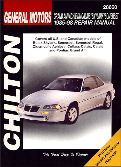
This Chilton DIY repair and service manual, covers 1985-1998 U.S. and Canadian models of the following GM vehicles:
Book Excerpt: 1985-1998 Skylark, Somerset, Regal, Achieva, Calais, Grand Am Repair Manual DRIVEABILITY AND EMISSIONS CONTROL
DRIVE TRAIN
Subject: 1985, 1986, 1987, 1988, 1989, 1990, 1991, 1992, 1993, 1994, 1995, 1996, 1997, 1998 Buick Skylark, Somerset, Regal; Olds Achieva, Cutlass Calais; Pontiac Grand Am service, maintenance, repair. ISBN-10: 0801991064 | ISBN-13: 9780801991066 | Chilton 28660
- Buick: Skylark, Somerset, and Somerset Regal
- Oldsmobile: Achieva, Cutlass Calais, and Calais
- Pontiac: Grand Am
Book Excerpt: 1985-1998 Skylark, Somerset, Regal, Achieva, Calais, Grand Am Repair Manual DRIVEABILITY AND EMISSIONS CONTROL
REMOVAL AND INSTALLATION PORTED AND NEGATIVE BACKPRESSURE EGR VALVES
(See Figures 21, 22, 23 and 24)DIGITAL EGR VALVE
- Disconnect the negative battery cable.
- If necessary for valve access, remove the air cleaner assembly.
- If equipped, remove the EGR valve cover.
- Tag and disconnect the necessary EGR valve hoses and wiring.
- Unfasten the EGR valve retaining bolts.
- Remove the EGR valve. Discard the gasket.
- Buff the exhaust deposits from the mounting surface and around the valve using a wire wheel.
- Remove deposits from the valve outlet.
- Clean the gasket material from the mounting surfaces of the intake manifold and valve assembly.
TO INSTALL- Using a new gasket, position the EGR valve on the manifold.
- Install the retaining bolts, and then tighten them to 16 ft. lbs. (22 Nm).
- Connect the wiring and hoses.
- Place the cover on the valve, if equipped.
- Install the air cleaner assembly.
- Connect the negative battery cable.
(See Figure 25)
- Disconnect the negative battery cable.
- Detach the electrical connections at the solenoid.
- Unfasten the two base-to-pad retaining bolts/screws, and then remove the EGR valve from the engine. Remove and discard the gasket.
- Clean the gasket mating surfaces.
TO INSTALL- Position a new EGR valve gasket, aligning it with the holes.
- Install the bolts, aligning them through the EGR valve assembly and cast EGR pad of the upper intake manifold and into the pipe assembly. Tighten the bolts to 18 ft. lbs. (25 Nm).
- Attach the electrical connections to the solenoid.
- Connect the negative battery cable.
DRIVE TRAIN
AUTOMATIC TRANSAXLE | GENERAL INFORMATION An internal combustion engine can only produce power within a certain speed range. Typically, engines have a torque band of approximately 2500 to 4500 rpm. To make use of the narrow torque band, a collection of reduction gears are used to keep the engine within its peak operating range as the vehicle speed increases and decreases. The gears inside the transaxle are configured in a "planetary" manner. Varying drive ratios are achieved through the use of hydraulically actuated clutch packs and bands that manipulate the planetary gears.
ADJUSTMENTS THROTTLE VALVE CABLE | EXCEPT 2.3L ENGINE
(See Figures 32, 32 and 34)
- Disconnect the negative battery cable.
- Depress and hold the adjustment tap at the Throttle Valve (TV) cable adjuster.
- Release the throttle lever by hand to its full travel position. On the 2.5L engine, press the accelerator pedal to the full travel position.
Subject: 1985, 1986, 1987, 1988, 1989, 1990, 1991, 1992, 1993, 1994, 1995, 1996, 1997, 1998 Buick Skylark, Somerset, Regal; Olds Achieva, Cutlass Calais; Pontiac Grand Am service, maintenance, repair. ISBN-10: 0801991064 | ISBN-13: 9780801991066 | Chilton 28660
TABLE of CONTENTS:
Introduction: About this manual | Introduction | Vehicle identification numbers | Maintenance techniques, tools and working facilities | Buying parts | Jacking and towing | Anti-theft audio system | Booster battery (jump) starting | Conversion factors | Automotive chemicals and lubricants | Safety first! | Troubleshooting
- Tune-up and routine maintenance
- Engine and overhaul procedures
- Cooling, heating and air-conditioning systems
- Fuel and exhaust systems
- Engine electrical systems
- Emissions control systems
- Transmission
- Brakes
- Suspension and steering systems
- Body
- Chassis electrical system
- Wiring diagrams


