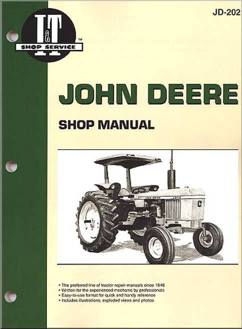
Penned for the experienced mechanic by professionals, the John Deere Shop Manual JD-202 available at The Motor Bookstore comes in a format that is easy to use for a handy reference that will benefit anybody who wants to tackle maintenance and repair of their tractor themselves. This I & T tractor manual is 320 pages with plenty of diagrams and photos to illuminate whatever aspect of your tractor your maintenance or repair work is focused on. Detailed illustrations include exploded views and the manual features tips and guidance on how to maintain the engine, electrical system, cooling system, differential, axles, hydraulics and more.
Learn the proper maintenance schedule for the Deere 2510, or any of the other models covered, including 2040, 2520, 2240, 2440, 2630, 2640, 4040, 4240, 4440, 4640, 4840.
This John Deere Tractor Repair Manual covers the following models:
- John Deere 2040
- John Deere 2510
- John Deere 2520
- John Deere 2240
- John Deere 2440
- John Deere 2630
- John Deere 2640
- John Deere 4040
- John Deere 4240
- John Deere 4440
- John Deere 4640
- John Deere 4840
Note: this tractor repair manual does not include wiring diagrams.
Book Excerpt: John Deere Tractor Repair Manual 2040, 2510, 2520, 2240, 2440, 2630, 2640, 4040, 4240, 4440, 4640, 4840 PINION SHAFT
140. RandR and OVERHAUL. To remove the transmission pinion shaft, remove the input shaft as in paragraph 139 and the differential as in paragraph 144. With differential removed, remove oil line, nut (43-Fig. 132), bearing (42), shims (40) and spacer (39). Use a screwdriver and turn thrust washers until splines of thrust washers are indexed with splines of countershaft. Pull countershaft rearward and remove parts from transmssion case as they come off shaft. Bearing cup (25) and shims (26) can be removed from housing by bumping cup rearward. Be sure to keep shims (26) together as they control the bevel gear mesh position. Bearing cup (41) can be removed from housing by bumping cup forward. Check all gears and shafts for chipped teeth, damaged splines, excessive wear or other damage and renew as necessary. If pinion shaft is renewed, it will also be necessary to renew the differenetial ring gear and right hand differential housing as these parts are not available separately. Bearing (24) is installed with large diameter toward gear end of shaft. Note: Mesh (cone point) position of the pinion shaft and main drive bevel pinion gear is adjusted with shims (26) located between rear bearing cup (25) and housing. If new drive gears or bearings are installed, the mesh position is correctly adjusted by installing two 0.010 inch thick shims (26 - Fig. 132). If same pinion shaft and bearing are installed, reinstall the same shims (26). Install pinion shaft and adjust shaft bearing preload as follows: Use Fig. 132 as a guide and with bearing (24) on pinion shaft, start shaft into rear of housing. With shaft about half-way into housing, place 1st and 5th speed gear (27) on shaft with teeth for shift collar (29) toward front. Place the thickest thrust washer (28) on shaft, then install coupling sleeve (30) and shift collar (29).
Subject: John Deere farm tractor service, maintenance, repair. ISBN-10: 0872883663 | ISBN-13: 9780872883666
- Detailed illustrations and exploded views
- Troubleshooting sections covering most models
- Brakes
- Cooling system
- Differential
- Electrical system
- Engine
- Final drive
- Axles
- Hydraulics
- Transmission
- Condensed service data information
- Detailed index
- Accurate information in a concise, easy-to-use format
- Durable, coated paper stands up to messy shop jobs


