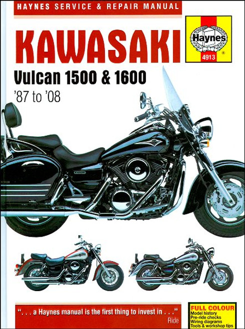
The 1987-2008 Kawasaki Vulcan 1500 and 1600 repair manual by Haynes, covers the following motorcycle models:
Book Excerpt: 1987-2008 Kawasaki Vulcan 1500, Vulcan 1600 Repair Manual ENGINE, CLUTCH AND TRANSMISSION
ELECTRICAL SYSTEM
Subject: 1987, 1988, 1989, 1990, 1991, 1992, 1993, 1994, 1995, 1996, 1997, 1998, 1999, 2000, 2001, 2002, 2003, 2004, 2005, 2006, 2007, 2008 Kawasaki Vulcan 1500, Vulcan 1600 service, maintenance, repair. ISBN-10: 1844259137 | ISBN-13: 9781844259137 | Haynes 4913
- Kawasaki Vulcan VN1500, 1987-1999
- Kawasaki Vulcan VN1500 Classic, 1996-2004
- Kawasaki Vulcan VN1500 Classic Fl, 2000-2008
- Kawasaki Vulcan VN1500 Nomad/Classic Tourer, 1998-2001
- Kawasaki Vulcan VN1500 Nomad/Classic Tourer Fl, 2000-2004
- Kawasaki Vulcan VN1500 Drifter, 1999-2004
- Kawasaki Vulcan VN1500 Mean Strek, 2002-2003
- Kawasaki Vulcan VN1600 Classic, 2003-2008
- Kawasaki Vulcan VN1600 Mean Strek, 2004-2008
- Kawasaki Vulcan VN1600 Nomad/Classic Tourer, 2005-2008
Book Excerpt: 1987-2008 Kawasaki Vulcan 1500, Vulcan 1600 Repair Manual ENGINE, CLUTCH AND TRANSMISSION
TRANSMISSION SHAFTS - DISASSEMBLY, INSPECTION AND REASSEMBLYVN1500A AND B AND CLASSIC D MODELS | 4 SPEED TRANSMISSION
- Remove the transmission shafts from the crankcase (see Section 32). Always disassemble the transmission shafts separately to avoid mixing up the components.
INPUT SHAFT DISASSEMBLY
- Remove the snap-ring from the left end of the shaft and slide the needle bearing off (see illustration).
- Slide the thrust washer and the 4th and 2nd gear pinions off the shaft.
- Remove the circlip securing the 3rd gear pinion, and then slide the washer and the pinion off the shaft.
- The 1st gear pinion is integral with the shaft.
INSPECTION- Wash all of the components in clean solvent and dry them off. Blow through the oil holes with compressed air if available.
- Check the needle bearing, referring to Tools and Workshop Tips in the Reference Section if required replace it with a new one.
- Check the gear teeth for cracking, chipping, pitting and other obvious wear or damage. Any pinion that is damaged as such must be replaced with a new one.
- Inspect the dogs and the dog holes in the gears for cracks, chips, and excessive wear especially in the form of rounded edges (see illustration). Make sure mating gears engage properly. Replace the paired gears as a set if necessary.
- Check for signs of scoring or bluing on the pinions, bushes where fitted, and shaft. This could be caused by overheating due to inadequate lubrication. Make sure the oil retention dimples on fitted bushes are visible (see illustration) - if not the bush is worn. Check that all the oil holes and passages are clear. Replace any damaged or worn pinions or bushes.
- Check that each pinion moves freely on the shaft or its bush where fitted but without undue free play. Check that each bush moves freely on the shaft but without undue free play.
- The shaft is unlikely to sustain damage unless the engine has seized, placing an unusually high loading on the transmission or the machine has covered a very high mileage. Check the surface of the shaft, especially where a pinion turns on it, and replace the shaft if it has scored or picked up, or if there are any cracks. Damage of any kind can only be cured by replacement.
- Check the washers and replace any that are bent or worn. Use new ones if in any doubt. Replace all circlips with new ones.
ELECTRICAL SYSTEM
OIL PRESSURE SWITCH - CHECK AND REPLACEMENT CHECK
- If the oil pressure warning light fails to operate properly, check the oil level and make sure it is correct.
- If the oil level is correct, disconnect the wire from the oil pressure switch, which is located in the back of the crankcase to the left of the oil filter (see illustration). Turn the ignition switch ON and ground (earth) the end of the wire. If the light comes on, the oil pressure switch is defective and must be replaced with a new one. Note that on all except VN1500A and B and Classic D, E1 and F1 models the system is fitted with a three second delay unit to prevent the light coming on during heavy braking and acceleration when oil surge occurs.
- If the light does not come on, check the oil pressure warning light bulb where fitted (other models have an LED), and check the wiring and connections between the oil pressure switch, delay unit where fitted, and the light, and between the light and the junction box (see the wiring diagrams at the end of this manual).
- On all except VN1500A and B and Classic D, E1 and F1 models if all is good so far replace the delay unit with a new one.
Subject: 1987, 1988, 1989, 1990, 1991, 1992, 1993, 1994, 1995, 1996, 1997, 1998, 1999, 2000, 2001, 2002, 2003, 2004, 2005, 2006, 2007, 2008 Kawasaki Vulcan 1500, Vulcan 1600 service, maintenance, repair. ISBN-10: 1844259137 | ISBN-13: 9781844259137 | Haynes 4913
TABLE of CONTENTS:
LIVING WITH YOUR KAWASAKI VULCAN
- Identification numbers
- Buying spare parts
- Pre-ride checks
- Engine oil level
- Brake fluid levels
- Tires
- Bike specs
- Routine maintenance and servicing
- Specifications
- Lubricants and fluids
- Maintenance schedule
- Component locations
- Maintenance procedures
- Engine, clutch and transmission
- Carburetor
- Fuel Injection System
- Exhaust systems
- Ignition system
- Frame and suspension
- Brakes, wheels and final drive
- Fairing and bodywork
- Electrical system
- Color wiring diagrams
- Tools and workshop tips
- Security
- Storage
- Troubleshooting


