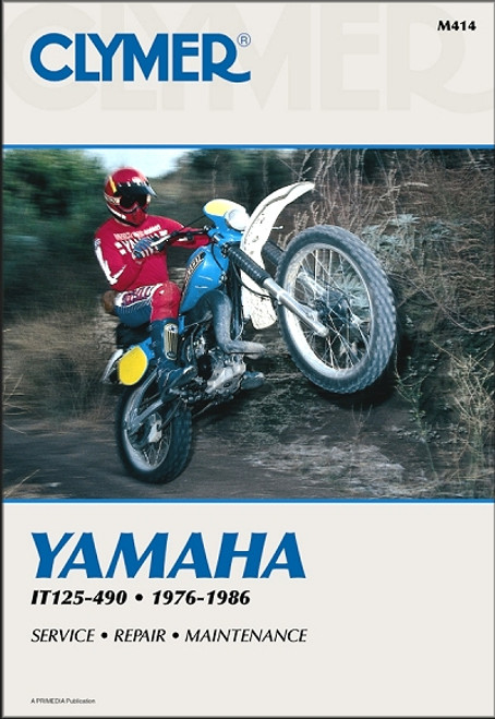
The 1976-1986 Yamaha IT125-490 off-road bike repair manual by Clymer, covers the following models:
Book Excerpt: 1976-1986 Yamaha IT125, IT175, IT200, IT250, IT400, IT425, IT465, IT490 Repair Manual ENGINE
REAR SWING ARM
Subject: 1976, 1977, 1978, 1979, 1980, 1981, 1982, 1983, 1984, 1985, 1986 Yamaha IT125, IT175, IT200, IT250, IT400, IT425, IT465, IT490 service, maintenance, repair. ISBN-10: 0892873302 | ISBN-13: 9780892873302 | Clymer M414
- Yamaha IT125, 1980-1981
- Yamaha IT175, 1977-1983
- Yamaha IT200, 1984-1986
- Yamaha IT250, 1977-1983
- Yamaha IT400, 1976-1979
- Yamaha IT425, 1980
- Yamaha IT465, 1981-1982
- Yamaha IT490, 1983-1984
Book Excerpt: 1976-1986 Yamaha IT125, IT175, IT200, IT250, IT400, IT425, IT465, IT490 Repair Manual ENGINE
REAR VALVE ASSEMBLY All IT engines are equipped with a power reed valve assembly that is installed in the intake port of the cylinder. The smallest displacement engine (IT125) has 2 reeds per side for a total of 4. The largest displacement engine (IT175 through IT425) have 3 reeds per side for a total of 6. Particular care must be taken when handling and repairing the reed valve assembly. A malfunctioning reed valve will cause severe performance loss as well as contribute to a too lean mixture. REMOVAL/INSTALLATION
- Remove the cylinder head and cylinder as described under Cylinder Removal/Installation in this chapter.
- Remove the allen head (Figure 57) or hex head bolts (Figure 58) securing the reed valve assembly to the cylinder.
- Carefully remove the reed valve assembly from the cylinder. If the assembly is difficult to remove, use a drift or broad?tipped screwdriver and gently tap the side of the assembly to help break it loose from the gasket and cylinder.
REAR SWING ARM
The rear swing arm is manufactured either of aluminum or steel; this varies with different models and years. Aluminum and steel swing arms are basically the same and removal and installation of both are covered in the same procedure. Disassembly, inspection and assembly are different and are covered separately. In time, the bearings or bushings will wear beyond the service limits and will have to be replaced. The condition of the bearings or bushings can greatly affect handling performance and if worn ones are not replaced they can produce erratic and dangerous handling. Common symptoms are wheel hop, pulling to one side during acceleration and pulling to the other side during braking.
SWING ARM REMOVAL/INSTALLATION NOTE: This procedure is shown with both types of swing arms.
- Remove the rear wheel and drive chain as described under Rear Wheel Removal/Installation in this chapter.
- Remove the cotter pin(Figure 36) on the end of the upper mounting pin.
- Pull the pin out (Figure 37) and gently let the swing arm pivot down (Figure 38).
Subject: 1976, 1977, 1978, 1979, 1980, 1981, 1982, 1983, 1984, 1985, 1986 Yamaha IT125, IT175, IT200, IT250, IT400, IT425, IT465, IT490 service, maintenance, repair. ISBN-10: 0892873302 | ISBN-13: 9780892873302 | Clymer M414
TABLE of CONTENTS:
- General Information
- Troubleshooting
- Lubrication, Maintenance and Tune-up
- Engine
- Clutch and External Gearshift Linkage
- Transmission and Internal Shift Mechanism
- Fuel and Emission Systems
- Exhaust System
- Electrical System
- Wheels, Tires and Drivetrain
- Front Suspension and Steering
- Rear Suspension
- Brakes
- Body and Frame
- Wiring Diagrams


